
Taking apart the PH-2 is easy and its sophisticated design is actually easy to disassemble for modifications. There are four screws on the bottom, plus 1 more inside to remove. Then, tackle the pots, jacks, and footswitch. For each of these pictures, you can get a super close-up, high resolution view by double-clicking on the photo.
STEP 1: Remove the Screws Remove the 4 screws on back; pull out the battery compartment top to expose 2 more hidden screws. Remove the back plate and the black plastic insulator sitting between the backplate and the circuit board. Remove the 4 screws on back; pull out the battery compartment top to expose 2 more hidden screws. Remove the back plate and the black plastic insulator sitting between the backplate and the circuit board.Make sure to save all the screws and especially the insulator! Once you have the insulator off, you can gently pry up on the back of the circuit board - there are no screws holding the PCB in place. | ||
STEP 2 Remove the LED PCB and Jack/Pot Nuts  Pull up on the main PCB to expose the potentiometer PCB and LED PCB. The LED PCB is held in place by a single screw. Pull up on the main PCB to expose the potentiometer PCB and LED PCB. The LED PCB is held in place by a single screw.Once you get this screw out, you can pull out the PCB and then pull apart and separate the main PCB and potentiometer wiring harness from the unit. Next, remove the nuts from the input and output jacks. Pull off the plastic knobs and remove the nuts for the potentiometers. | ||
STEP 3: Disconnect the footswitch  De-solder the purple and black wires going to the footswitch. Once you have them off, press the two tabs on either side of the switch to free it and push out down toward the battery compartment. Once it comes out you can thread the battery connecter harness back out through the switch hole. This will completely free the circuit board, pots and jacks. | ||
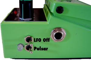
STEP 4: Drill out the Mod Holes  This is where you have some decisions to make. Here I have drilled 3 of the 4 holes necessary. The black lines on the inside were drawn as keepouts so I know where the pot assembly is. This is where you have some decisions to make. Here I have drilled 3 of the 4 holes necessary. The black lines on the inside were drawn as keepouts so I know where the pot assembly is.I chose to drill a hole and show the LED used in the Pulsar mod because it actually flashes during operation. This was an optional step and you can ignore it if you need to. |


No comments:
Post a Comment