 The Output Gain mod adds more power. Effects like Chorus and Phaser never have enough ooomph for me and tend to muddy things up. This mod will help it stand out! The Output Gain mod adds more power. Effects like Chorus and Phaser never have enough ooomph for me and tend to muddy things up. This mod will help it stand out!The mod is centered around R79 which sets the gain for the phaser output (both wet and dry simultaneously). Interestingly, it is noted as a 10k resistor on the schematic but mine had a 27k resistor instead, which lowered the gain. For this mod, wire the switch to choose either the 27k stock resistor, or the 15k resistor chosen to be about 1/2 the normal value for 6dB of added gain. Note you could also jumper another 27k resistor across it as well. | |
STEP 1: Locate R79 and remove it  R79 is located near the ribbon connector side of the PCB just below the SIP op-amp. Flip the PCB over and de-solder R79 and remove it from the PCB leaving clean through-holes for wiring the mod. R79 is located near the ribbon connector side of the PCB just below the SIP op-amp. Flip the PCB over and de-solder R79 and remove it from the PCB leaving clean through-holes for wiring the mod. | |
STEP 2: Add Mod wires in place of R79  Cut a pair of mod wires (jumpers). Strip, tin, and insert one wire into each hole left by R79. These wires will travel out to the switch where the other resistors will be located. Its much easier to wire the resistors to the switch than to the cramped PCB. Cut a pair of mod wires (jumpers). Strip, tin, and insert one wire into each hole left by R79. These wires will travel out to the switch where the other resistors will be located. Its much easier to wire the resistors to the switch than to the cramped PCB. | |
STEP 3: Wire the Switch  The switch is wired with the original 27k resistor on one side, and the new 15k resistor on the other. They are soldered together at one end. Solder this end with a heat shrink tubing to one of the R79 mod wires, and solder the center pin of the switch to the other R79 mod wire. The switch is wired with the original 27k resistor on one side, and the new 15k resistor on the other. They are soldered together at one end. Solder this end with a heat shrink tubing to one of the R79 mod wires, and solder the center pin of the switch to the other R79 mod wire. | |
STEP 4: Wire and Test Fit  Mount the switch. I completely enclosed the resistors inside a big red piece of heat shrink tubing. You need to insulate it from shorting with any other PCB components which will be very close to it, once reassembled. Mount the switch. I completely enclosed the resistors inside a big red piece of heat shrink tubing. You need to insulate it from shorting with any other PCB components which will be very close to it, once reassembled. | |
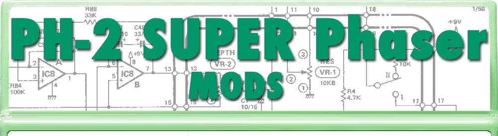
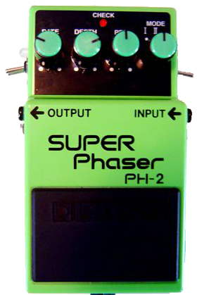
PH-2 Superphaser Mods
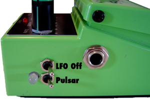
The two issues I always had with my phaser were 1) it gets mushed out in the mix and 2) it is a one-trick-pony that I really only used for rotating speaker emulations. These mods gave me a whole new device, especially my Pulsar mod.
|
|
These mods are of my own design and I have not seen them anywhere else. The schematics are well documented and available all over the internet. BOSS, SUPERPhaser, and PH-2 ARE TRADEMARKS OF THE ROLAND CORPORATION AND ARE USED FOR REFERENCE ONLY. THIS SITE IS NOT AFFILIATED WITH THE ROLAND CORPORATION IN ANY WAY.

Output Gain Mod
Subscribe to:
Post Comments (Atom)


This comment has been removed by the author.
ReplyDeleteThis comment has been removed by the author.
ReplyDeleteLove it, made my favorite phaser even better!
ReplyDeleteThanks!
I was wondering if Miguel's comment is accurate?
ReplyDeletehe just want to know what type of switch to used with this mod (On-Off-On) or (on-on-on)
ReplyDelete